|
|||||||||||||||||||||||||||||||||||||||||||||||||||||||||||||||||||||||||||||||||||||||||||
| volume 7, number 2: SUMMER 2009 in this issue: |
|
||||||||||||||||||||||||||||||||||||||||||||||||||||||||||||||||||||||||||||||||||||||||||
|
[Links followed by * open new browser windows.] |
|||||||||||||||||||||||||||||||||||||||||||||||||||||||||||||||||||||||||||||||||||||||||||
|
|
|||||||||||||||||||||||||||||||||||||||||||||||||||||||||||||||||||||||||||||||||||||||||||
|
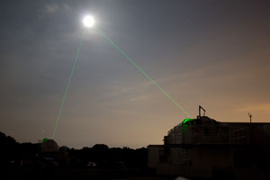
Like other instruments on the Lunar Reconnaissance Orbiter (LRO)*, the Lunar Orbiter Laser Altimeter (LOLA)* has evolved from technology developed for previous NASA spacecraft. Thanks to several upgrades, LOLA is producing data that honors and advances the tradition of its predecessors. LOLA is one of seven instruments on LRO that are helping to characterize the lunar surface and provide important data, paving the way to return humans to the moon. LOLA’s primary objective is to measure the lunar surface elevation and produce a geodetic topographic map of the moon for lunar science studies and future explorations. This will aid future missions by providing topographical data for safe landings and enhance exploration-driven mobility on the moon. Conceived and built by a team of engineers and scientists at NASA’s Goddard Space Flight Center, LOLA is a descendant of the Mars Orbiter Laser Altimeter (MOLA)* that was flown on the Mars Global Surveyor spacecraft and the Mercury Laser Altimeter (MLA)* that is currently deployed on MESSENGER (NASA’s MErcury Surface, Space ENvironment, GEochemistry, and Ranging mission)*. LOLA performs similar tasks to that of its predecessors, but it does so with a three to five times greater level of accuracy than MOLA and timing resolution that is significantly better than MLA. The primary upgrade to LOLA is the use of a diffractive optical element (DOE) to split a single laser pulse into five beams, producing five independent measurements across a swath and creating a more detailed map of the local topography within a region.
LOLA also is the first laser altimeter on a NASA spacecraft to carry a one-way laser ranging (LR) system that utilizes a small telescope on a high-beam antenna to optically detect and timestamp laser pulses from Earth, determining LRO’s precise orbit position. “Knowing the precise location of the spacecraft helps to improve the resolution of the topographic measurement made by LOLA,” said John Cavanaugh, LOLA system’s engineer. “The orbit of the craft is constantly changing by meters, and determining the exact location of the satellite is essential. If you make that measurement without knowing the location of the spacecraft, you don’t have an absolute reference for the topography.” These upgrades not only are helping LOLA obtain data that will assist future lunar missions, but they are also providing stunning images that will enhance the public’s understanding of the moon. Members of the LOLA project team have been working to pass along the advancements from LOLA to future NASA missions—including the Geoscience Laser Altimeter System (GLAS)* on the Ice, Cloud, and land Elevation Satellite-II (ICESat-II)*—and they have been working closely with Goddard’s Innovative Partnerships Program (IPP) Office on potential commercialization of the LOLA technology. “The lessons learned from this mission are important for the development of the next generation of instruments,” said Ramos-Izquierdo. “Future missions will be able to benefit from LOLA, just like LOLA benefited from MOLA and MLA.”
|
|||||||||||||||||||||||||||||||||||||||||||||||||||||||||||||||||||||||||||||||||||||||||||
|
|
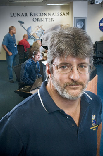
Craig Tooley As the Lunar Reconnaissance Orbiter (LRO) project manager at NASA’s Goddard Space Flight Center, Craig Tooley is responsible for the development and execution of the LRO mission. Tooley talks about this groundbreaking mission and how LRO went from inception to launch in less than 4 1/2 years. Could you tell us a little bit about the projects you worked on before LRO? I came to Goddard in 1983 after receiving a bachelor of science in mechanical engineering from the University of Evansville in Indiana and have been here ever since, earning a master’s degree in mechanical engineering at the University of Maryland along the way. I spent the first half of my career working on space shuttle-related projects, including serving as the mission manager and mechanical lead for five successful Spartan solar-science missions. After working in the shuttle world, I moved on to be the deputy project manager for the Triana mission*, an Earth-observing satellite to be placed at a sun-earth libration point that is fully developed and that NASA, together with NOAA , now plans to launch in 2012. I then joined the Hubble servicing group, where I worked as part of the EVA servicing team that developed procedures and trained astronauts for the successful Hubble Servicing Mission 3B in 2002. Immediately before being asked to start up LRO in 2004, I led the Hubble Space Telescope Instrument Development Office, overseeing the development of instruments to be installed during the fourth and final Hubble servicing mission. How would you describe your day-to-day responsibilities as LRO project manager? It has been an honor and a real pleasure to be the project manager for this mission. I have the joy of getting to be proud of over 300 people who dedicated their lives to LRO’s success over the past 4 1/2 years. The development of the LRO spacecraft was an in-house mission, so my role as the project manager prior to launch was a little different than for a mission with a prime contractor, where the spacecraft is procured. Goddard essentially served as the prime contractor, so in addition to keeping an eye on programmatic aspects of the mission such as budget and schedule, I spent much of my time directly working with the engineering and development team that designed, fabricated, and developed the spacecraft, which in many ways has been the most satisfying part of the mission. Now that the spacecraft is flying, I serve as a mission director with responsibility for managing operations, making sure that all of the wheels are turning properly and everything is going as planned. The operations team does most of the post-launch work, although the systems engineers and the engineering team are engaged during the initial commissioning phase. Within the next few months, my role likely will be transitioned to the Space Science Mission Operations (SSMO) group here at GSFC. How did the scope of the LRO mission evolve? When LRO originally was envisioned in 2004, it was designed to be one in a series of unmanned missions to the moon. We were part of a stable of projects under a larger program here at GSFC. LRO evolved when NASA’s Exploration Systems Mission Directorate (ESMD)* decided that we didn’t need to fly any additional unmanned missions to the moon, and it went from being embedded in an integrated program to being a stand-alone project here at Goddard.
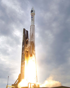
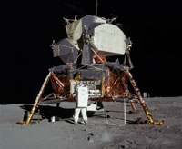
How is LRO paving the way for NASA to go back to the moon and beyond? The primary objective of LRO is to conduct investigations to prepare for future lunar exploration. LRO will scout for safe and compelling lunar landing sites, locate potential resources with special attention to the possibility of water ice, and characterize the effects of prolonged exposure to the lunar radiation environment. LRO’s instrument payload consists of seven scientific instruments from partner institutions around the nation and the globe, including one instrument contributed by the Institute for Space Research in Moscow. These instruments will provide lunar imagery, topography, temperatures, and more. Returning to the moon with LRO will also enable the pursuit of scientific activities that address fundamental questions about the history of Earth, the solar system, and the universe—and about our place in them. LRO was launched on an Atlas V 401 rocket in June and will be in a commissioning orbit until September 15, while we test and calibrate equipment. It then will move to its final orbit, a circular polar orbit approximately 50 km (31 miles) above the surface of the moon. LRO will spend a year in the NASA Exploration mission, collecting detailed information about the moon and its environment. Once the Exploration phase is completed, NASA Science will take the keys to LRO and fly it for at least 2 years as a scientific, discovery-driven project.
The schedule for LRO was even more aggressive than the calendar would indicate. Unlike most missions, no preliminary studies or pre-Phase A work were done for LRO; we basically started with an objective and a blank slate. So, it was a very daunting schedule from the beginning. The most important factor in our success thus far is that we have an extraordinary team of people working on this project. We started with a core, almost turnkey team who were very familiar with each other and had experience working on projects with tight deadlines. When we assembled the initial LRO team, we were fortunate to get the individuals who we wanted to join our team as many of them sought to join the mission on their own initiative. As we brought in new people, they have assimilated into and resonated with the core team very well. Collectively and individually, we quickly developed open and honest dialogue, which was essential because often people had been asked to do things much faster than makes them comfortable. We’d push to make quick decisions as opposed to pondering for a long time, but we also keep the lines of communication open and make adjustments, even reverse decisions, when necessary. Other key factors are that the design of the mission as well as the hardware we used were engineered from the beginning to achieve our mission of exploring the moon and bringing back a multi-faceted atlas of information to enable the next steps for sending humans to the moon. The purpose of the mission was not to develop state-of-the-art technology—we just didn’t have time for that—though we did make some exciting technology advancements. As much as possible, we adapted existing technology to meet our needs. For example, the lunar instruments on LRO are all variations of instruments that are operating around other planets in the solar system. In areas where we moved the technology forward, we often drew from technology that was already in production at Goddard. In creating the spacecraft, for instance, we tapped into state-of-the-art technology that was already being developed at Goddard, including technology that was in production for the Solar Dynamics Observatory (SDO)*. Can you give some other examples in which LRO is responsible for the creation or evolution of state-of-the-art technology? The state of the art for precision-pointed high- gain multi-band communication antenna systems at GSFC now resides in LRO, thanks to the work that our engineers have done to develop the LRO High-Gain Antenna System (HGAS)*. HGAS began under the SDO and LRO adapted the design for the harsh lunar environment. The overall LRO communication system includes a newly designed Ka-band Travelling Wave Tube Amplifier (TWTA) which was in research development at NASA’s Glenn Research Center but was quickly moved forward to production for LRO. Now, the HGAS is being incorporated into the Global Precipitation Monitor (GPM)* mission, and many of our engineers are moving over to GPM, continuing the Goddard tradition of sharing technology so that the next mission does not have to reinvent the wheel. Also, the LRO flight software has been phenomenally successful. This has been one of the many highlights of the mission development. This is interesting because Project Managers often struggle with software development. When I talk with people outside of Goddard about the LRO software, they are sure that I am not telling them about the trouble, bugs, and unexpected costs we encountered while developing and implementing it. But our experience has been just the opposite. It has really been a joy to see how well the software has worked. Some of the software is new and but much of it is an evolution of what has been used here before, including the GSFC Core Flight Executive (cFE)* which is at the heart of the LRO flight software. The use of the cFE on LRO represents the first step in a much larger effort to provide an automated, platform-independent system that offers reusable software to all types of missions. [Read more about LRO technologies below.] How has the IPP Office and technology transfer in general been important for LRO? Goddard’s dedication to technology development, reuse, and sharing with next-generation missions—which is fostered and encouraged by the IPP Office—is one of the reasons that Goddard got the LRO mission. NASA knew that we could complete this mission quickly and successfully, in part because of Goddard’s track record for developing and promoting new technologies. I would point to HGAS and the Flight Software as specific examples. This mission has been a total team effort, and its success thus far is a significant accomplishment that should make everyone at Goddard proud.
|
||||||||||||||||||||||||||||||||||||||||||||||||||||||||||||||||||||||||||||||||||||||||||
|
Key LRO Technologies The Lunar Reconnaissance Orbiter (LRO) employs many advanced innovations developed at Goddard and in collaboration with other organizations. The applications and benefits for these technologies are advantageous for many other industries as well. The following section highlights several important LRO innovations.
Space Link Extension – Return Channel Frames Technical Details The Space Link Extension – Return Channel Frames (SLE-RCF) software library (GSC-15458-1) is being used by the LRO mission. It helps to monitor the health and safety of spacecraft by enabling space agency ground support and mission control centers to develop standardized and interoperable mission control applications for space telemetry data. The software library eliminates the need for missions to implement custom data communication designs to communicate with any ground station. The two main tasks accomplished via the SLE-RCF software library are processing user requests and receiving data from ground stations and ground support assets. The software library contains three layers:
The library accepts configuration or SLE-RCF directives from the user and responds accordingly. Incoming data, both telemetry frames and status messages, are processed and the appropriate callback routines are triggered by the library. Benefits
Applications
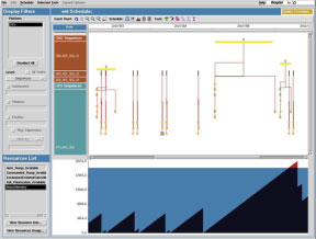
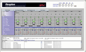
FlexPlan Mission Planning System Technical Details FlexPlan (GSC-15558-1) provides space agencies with a generic mission planning and scheduling software product that optimally organizes, schedules, and plans mission activities on the ground and onboard spacecraft—enabling ground operators to monitor the status of memory content onboard the spacecraft and the progress of planned activities throughout the mission. FlexPlan’s components are divided into two categories:
Users can define flight rules and mission rules as well as events, resources (including availability profiles), tasks, and operations of the mission. Using this information, master schedules are created to define specific scenarios in the mission and break the mission up into as many scenarios as the user specifies. Additional tools detect and resolve conflicts raised by the schedule generator. FlexPlan’s modular architecture allows its components to interact via a database, enabling various components to run at different times or concurrently by multiple operators. The FlexPlan architecture allows it to be easily extended with additional modules to support specific mission requirements or needs. It has a “pluggable” architecture that uses a publicly available XML interface to adapt easily to different types of missions without the need to configure the external interface to a specific input format. In addition, FlexPlan uses an ID system to track every output on the schedule to the input from which it was generated. This enables the system to update the status of all activities in a Web-based client. The operations team can change all the elements defined in the mission planning process during the operational lifetime of the mission. Benefits
Applications
LRO High-Gain Antenna System Technical Details Originally developed under NASA’s Solar Dynamics Observatory (SDO) program, enhancements in LRO’s High-Gain Antenna System (HGAS) incorporate a high data-rate Ka-band communication link as well as an S-band link for tracking, telemetry, and command of the spacecraft (GSC-15518-1). The HGAS features an axially symmetric dual reflector in a Cassegrain configuration, and a secondary reflector supported by struts over a primary reflector. This secondary reflector features an embedded Frequency Selective Surface (FSS) technology, which enables dual use of a single antenna. A Kaband feed horn is mounted at the base of the primary reflector, and energy fed to the horn radiates to the secondary reflector, illuminating the primary reflector. The antenna’s main radiation beam is formed predominantly by the energy distribution on the primary reflector. The S-band feed is housed inside the secondary reflector, at the focal point of the primary reflector. The secondary reflector is transparent to the S-band feed’s radiation and reflects the Ka-band radiation from the corrugated horn feed, located at its outer focal point. Radiation from the S-band feed passes seamlessly through the secondary reflector and is reflected by the primary reflector, forming the S-band beam. Benefits
Applications
LRO Dynamic Model Technical Details A Disturbance-Optics-Controls-Structures (DOCS) Toolbox* (GSC-15385-1) is a framework for performing integrated modeling of complex systems. It allows models from different disciplines (including but not limited to structural dynamics, optics, and controls) to be coupled, enabling an end-to-end prediction of system performance in the operational environment. For LRO, enhancement of the DOCS Toolbox allowed analysis of disturbances generated by a stepper motor mechanism. Known as the LRO Dynamic Model, this enhanced version incorporates stepper motor jitter dynamics to predict interaction between motor electrodynamics and observatory flexible modes. The notable approach of combining the manufacturer's stepper motor model with the LRO Jitter model, developed in the DOCS framework, was chosen because it leveraged existing models, allowed access to the DOCS suite of tools, and had a significant heritage. Using the LRO Dynamic Model enabled analysis of the LROinduced jitter for a range of actuator speeds, electrical and friction parameters, motor driver parameters, and structural parameters—enabling, under the worst-case assumptions for all parameters combined, the LRO still to be capable of meeting its optical pointing requirement. The DOCS Toolbox has been validated on the LRO Dynamic Model (comprised of finite element structural, optical, and control models). Benefits
Applications
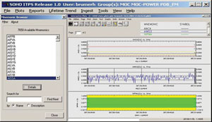
Integrated Trending and Plotting System Technical Details The Integrated Trending and Plotting System (ITPS) (GSC-15532-1) is a comprehensive tool for storage, extraction, and analysis of spacecraft housekeeping telemetry data. It reports information to engineers, ground controllers, and scientists regarding status and health of spacecraft and instruments. First developed for Landsat 7, ITPS was enhanced for LRO to provide a more flexible network interface supporting publish, subscribe, and messaging. This capability allows for plug-and-play and loosely coupled interfaces between the trending system and the rest of the mission operations tools. Thus, this software allows LRO to evolve as new technologies are developed or new versions are created, without affecting other components or systems in the mission management environment. ITPS can be used to monitor the spacecraft and components during pre-launch, ground-based integration and testing, and during launch and early orbit—enabling diagnostic, trending, or early issue identification. Benefits
Applications
Data Management System Technical Details The Data Management System (DMS) (GSC-15471-1), developed for the LRO mission, manages the flow of data products between LRO’s Mission Operations Center (MOC) components and between the MOC and the Science Operations Centers (SOCs). Managed data products include science products produced by the spacecraft, planning products used within the MOC and SOCs, load files to be uplinked to the spacecraft, etc. The DMS consists of a database, a web portal, and a “central agent” that run on the DMS server and “remote agent” applications that run on various computers within the MOC. The DMS is configured via an XML document that describes how the missions's products and models nominally flow. The remote agents monitor and control product flow. The central agent detects anomalies by comparing the actual flow as reported by the remote agents against the flow predicted by the model. The portal shows which products have been created and how they have flowed, allows authorized users to approve products so that they can continue their flow, and allows DMS administrators to tune the system. Benefits
Applications
|
|||||||||||||||||||||||||||||||||||||||||||||||||||||||||||||||||||||||||||||||||||||||||||
|
Goddard IPP Office Ignition Fund Awards NASA’s Goddard Space Flight Center has long valued and fostered the innovative spirit of its world-class scientists and engineers. This spirit has brought the world first-of-a-kind things—from pictures of the universe never previously imaged to planetary exploration capabilities beyond anything our ancestors thought possible. Goddard is renowned for having developed the most cutting-edge instruments for space and Earth exploration, inventing image analysis tools that have been recognized as Inventions of the Year, and providing state-of-the-art mission operations systems. Goddard’s Innovative Partnerships Program (IPP) Office established the Ignition Fund in 2009 to reignite the inventive spirit of our talented employees. The Ignition Fund was developed to nurture those technology ideas that are neither tested nor in a position to get NASA program or project funding. Awards of up to $50,000 were announced in May for the following individuals and their projects.
|
|||||||||||||||||||||||||||||||||||||||||||||||||||||||||||||||||||||||||||||||||||||||||||
|
Staff from IPP Office attended several events in summer 2009
50-Year Spinoff Art Contest (April 2009 – Greenbelt, Maryland)
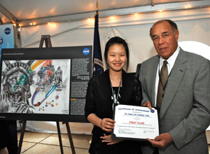
Goddard's IPP Office sponsored a special art contest for students in 6th through 12th grades, encouraging them to illustrate the utilization of technology investments through technology transfer, or spinoff. The winning submission, drawn by Ja Hyun "Ashely" Lim, a student at North County High School in Glen Burnie, Maryland, depicts how the IC531 anticorrosion coating that originally was developed to protect the launch pads at Kennedy Space Center from rust and pollution now also protects the Statue of Liberty. Next Steps in Managing Innovation (April 2, 2009 – Baltimore, Maryland) The IPP Office, Goddard’s partner Ocean Tomo, Inc., and IPXI, Inc. hosted this unique workshop that provided information about patents, licenses, and technologies to companies interested in NASA’s Small Business Innovative Research (SBIR) program. Company representatives were able to meet face-to-face with personnel from the IPP Office, Ocean Tomo, and prime contractors, to ask questions and gain insights about advancing their innovations for commercialization purposes. Federal Laboratory Consortium Annual Meeting (May 4-6, 2009 – Charlotte, North Carolina) IPP personnel attended this national meeting, attending training and panel sessions. IPP Office Chief Nona Cheeks taught a “Non-CRADA Technology Transfer Mechanisms” class and took part in a panel about auctioning federal lab IP licensing rights. Technology Transfer Manager Darryl Mitchell participated in the Human Interest Panel, where he highlighted Goddard's development of a compliant cable joint technology that was licensed to Enduro Medical Technology for use in a robotic physical therapy device called Secure Ambulation Module (SAM). Technical Interchange Forum (May 18, 2009 – Denver, Colorado) This meeting brought together personnel from across NASA’s IPP, the scientific and technological community, and Lockheed Martin Space Systems (LMSS) Company*. IPP employees and LMSS personnel presented their respective programs and technical capabilities. Both organizations used the event as a time to explore possible partnerships to advance both NASA and LMSS missions.
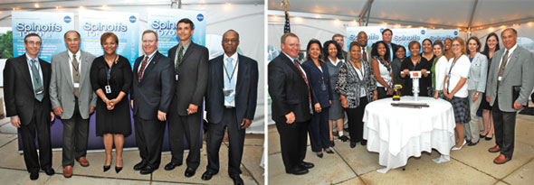
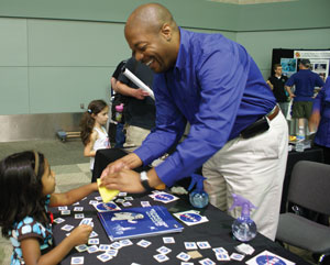
American Security Challenge (May 21, 2009 – Washington, DC) Representatives from Goddard’s IPP Office as well as other government agencies attended this event, which provides vehicles for emerging technologies to gain access to funding, contracts, or other awards to assist their vision and initiative in making the U.S. more secure. Technology Transfer Manager Ted Mecum gave a presentation about “Security Applications of Sensing and Detector Devices used for Earth and Space Science Programs” at the event. Maryland’s Place In Space (May 30, 2009 – Baltimore, Maryland) Celebrating Goddard’s 50th anniversary, Maryland’s Place in Space* was a public event at the Baltimore Convention Center. The IPP Office’s booth at this educational event attracted hundreds of visitors, including those studying robotics at local schools. These students were able to ask questions, learn all about technology transfer, and walk away with temporary NASA tattoos and coloring books illustrating the value of technology transfer. Goddard Celebrates 50 Years of Technology Spinoffs (June 4, 2009 – Greenbelt, Maryland) Commemorating the 50th anniversary of NASA’s Goddard Space Flight Center, the IPP Office hosted this evening event honoring the Goddard research that has developed into spin-off technologies, and highlighted significant technology transfer stories over the past five decades. The celebration included speakers from five partner organizations and IPP Office staff as well as local and regional economic development groups, technology transfer groups, innovators, and Goddard employees.
Rehabilitative Engineering and Assistive Technology Society of North America (June 23, 2009 – New Orleans, Louisiana) The RESNA* Annual Conference is an international, interdisciplinary conference about technology and disability. Goddard's IPP Office Technology Transfer Manager Darryl Mitchell gave a presentation about the Cable Compliant Joint technology and the patent license between Enduro Medical Technology and Goddard. The license resulted in Enduro’s SAM device for human and equine rehabilitation, which was made possible by the integration of the Cable Compliant Joint technology. Northrop Grumman Space Technology Forum (June 23-25, 2009 – Redondo Beach, California) IPP Office Chief Nona Cheeks attended this forum, which was themed "Demonstrating Advanced Capabilities for Next-Generation Systems." The event featured Northrop Grumman Aerospace Systems'* leading engineers and scientists who discussed progress in developing technologies that address the hardest problems and technical challenges facing government agencies today.
|
|||||||||||||||||||||||||||||||||||||||||||||||||||||||||||||||||||||||||||||||||||||||||||
|
|||||||||||||||||||||||||||||||||||||||||||||||||||||||||||||||||||||||||||||||||||||||||||
|
NASA Inventions and Contributions Board Awards Third quarter of fiscal year 2009 Tech Briefs Awards
Software Release Awards
Space Act Awards
|
|||||||||||||||||||||||||||||||||||||||||||||||||||||||||||||||||||||||||||||||||||||||||||
|
Innovators: Remember to report your new technologies through the online eNTRe system. eNTRe makes it convenient to file your New Technology Reports (NTRs) quickly, easily, and securely. Filing your NTRs enables the Innovative Partnerships Program (IPP) Office to support you by:
To get started, visit eNTRe* online.
|
|||||||||||||||||||||||||||||||||||||||||||||||||||||||||||||||||||||||||||||||||||||||||||
|
Chief: Nona Cheeks Goddard Tech Transfer News is the quarterly magazine of the Innovative Partnerships Program Office (Code 504) at NASA Goddard Space Flight Center in Greenbelt, Maryland. This magazine seeks to inform and educate civil servant and contractor personnel at Goddard*, as well as at Wallops Flight Facility* and the Independent Verification and Validation (IV&V) Facility*, about actively participating in achieving NASA’s technology transfer goals:
Please send suggestions or feedback about Goddard Tech Transfer News to the editor. All photographs in this publication are credited to NASA unless otherwise noted. |
|||||||||||||||||||||||||||||||||||||||||||||||||||||||||||||||||||||||||||||||||||||||||||
|
|||||||||||||||||||||||||||||||||||||||||||||||||||||||||||||||||||||||||||||||||||||||||||


 Nona Cheeks
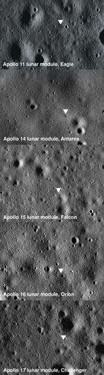

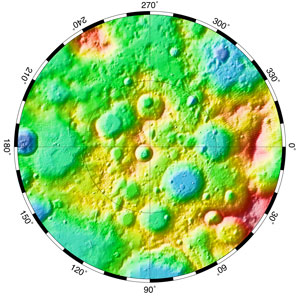
 “With each laser pulse, we get a more detailed understanding of the local slope and terrain, which gives us a better landing site scale topography with a single measurement,” said Luis Ramos-Izquierdo, LOLA optics lead. “The upgrade from a single laser in previous laser altimeters to five on LOLA is an exciting advancement that has already generated some amazing images of the south polar region of the moon.”
 How were you able to get LRO from concept to launch in less than 4 1/2 years?